Machining analysis and design of casting balls metal mould
The cast ball is the grinding medium widely used in ball mill, and its quality greatly influences grinding efficiency. The cast ball of dia120 in our country is generally formed by casting with metal mould with multi-cavity. The surface of the cast ball has a chilling layer and good comprehensive mechanical properties.
Our foundry’s annual output of dia120 cast ball is 5000 ~ 6000 tons, die(balls metal mould) consumption in about 300 sets. The traditional machining method is usually used in the machining of casting ball metal mould. The machining efficiency is low, the machining error is enormous, and the interchangeability is terrible. The Flash and dislocation of the parting surface seriously affect the appearance quality and grinding efficiency. In order to solve the machining error, different machining methods were tried to process the ball metal mould. After many experiments, a new method was found to process the ball metal mould directly on the vertical milling machine with the finger milling cutter through the synthetic motion.
1.The traditional machining method for metal mould
Using the lathe forming lathe tool to process a mold with three casting balls, the processing method is as shown in Fig. 1.
1.1 processing sequence
First, draw a three-bisector line on the circle of the ball metal mould and the ball mould, and then mark the bisector line on the ball mould. When a ball surface is finished, release the pressing plate, and rotate the ball mould to make the bisector line on the outer circle coincide with the one-bisector line, tighten the Platen, process the second sphere, and so on, finish the other spheres.
1.2 exist problems
The bisection between the spheres is ensured by drawing the lines, which causes the bisection error between the spheres to be bigger, and causes the casting dies to be out of alignment seriously, which affects the appearance quality.
2.Improved processing technology
2.1 Principle of Material Processing
In the vertical milling machine through the synthesis movement, with the finger milling cutter processing a mold.
2.2 Milling machine tooling
2.2.1 Cast balls metal mould
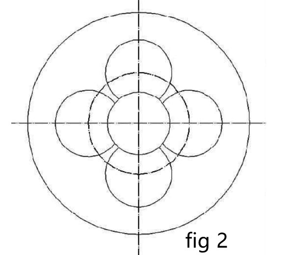
Below dia120 ball mold usually, four or six sub-multi-cavity, as shown in Figure 2, processing to ensure equal sub-angle and circle diameter.
2.2.2 Milling machine tooling
sing X53K vertical milling machine (figure 3), the inclination f angle of spindle 1 can be adjusted (find the center of the circle) and move laterally by means of the translation of Table 6. The universal indexing head five is fixed on the worktable, and the cutter is perpendicular to the spindle.
2.2.3 Center position
The half-sphere die is clamped on the universal indexing head chuck. The center of the machining sphere center radius is located on the central axis of the indexing disk. The centerline of the milling cutter is coincident by the front-back-left-right movement of the milling machine platform, lock the machine before and after, left and right limit, so that the machine can only move up and down.
3.Processing technology
3.1 processing sequence
First, according to the drawing requirements, machining the upper and lower plane and the inner hole to the size, and then assembling the jig to the milling machine for processing. First, the milling cutter tip is aligned to the center of the ball socket. The spindle rotates to realize the vertical and horizontal movement of the milling cutter; simultaneously, the circular cutting of the die is realized by rotating the handle at a constant speed. The combined movement of these three directions forms a spherical surface. When the 1 # spherical surface is finished, the pressing plate is released, and the upper die 3 is rotated together with the hemisphere die 90 °, the other 3 # and 4 # spheres are machined in this way.
3.2 Angle positioning
The angle can be calculated according to the geometric triangle relation and the milling cutter size, as shown in Figure 4.
a:∠AOB = 2a sin2a = AB / AO = d / 2 / R = d/ 2 R = d/ D,Radius of the ball to the knife e/ 2:e/ 2 = R cosa
4.Conclusion
(1) the optimization and precise control of the process parameters is an important means to produce a high-quality mold with one metal mold and multi-ball casting.
(2) the advantage of profile-copying technology is that the principle of profile-copying is to use the side edge of the finger-milling cutter as the main cutting edge to process the different diameter hemispheres without the need to buy forming tools. The working procedure is simple, and the production efficiency is high; the ball mold parting surface has high precision control, good interchangeability, and is convenient for batch processing, which greatly saves the cost of metal mold processing.


